A drawing where welds are described „by eye” usually ends the same way: the welder does what he thinks is reasonable, quality control has a different opinion, and the customer has yet another. Weld designation according to EN ISO 2553 resolves this dispute before anyone strikes the arc. A single symbol indicates what type of weld to make, from which side, how thick and how long, and by which method.
This text is a cheat sheet for people who read or commission drawings: owners and production managers in metal plants. Symbols are described verbally and in tables, without graphics; the goal is not to replace the standard, but rather to provide a quick reminder of what a triangle, two lines, or a flag next to a reference line means.
Finally, we explain why clear marking of welds on a technical drawing is a prerequisite for transferring welding to a robot or laser welder.
What does a weld designation consist of?
The full weld symbol according to EN ISO 2553 has four elements. Each carries different information, and it is important to be able to recognize each one.
| Sign element | What does it look like? | What does it mean? |
|---|---|---|
| Arrow | A diagonal line ending in an arrowhead that touches the joint | Indicates the location of the weld on the drawing; the side from which the arrow originates is the „arrow side” |
| Reference line | A horizontal continuous line to which the arrow connects | A horizontal reference line, above which the weld symbol and its dimensions are placed |
| Identification line | A dashed line parallel to, below, or above the reference line | In the European system, it indicates the „other side” of the joint, opposite the arrow |
| Tail | A fork at the end of the reference line | Space for additional information: process number according to ISO 4063, reference to welding instructions |
The reading principle in the European system is: the symbol next to the solid line indicates the weld on the arrow side; the symbol next to the dashed line indicates the weld on the opposite side; symbols on both sides indicate a double-sided weld. For a symmetrical weld, the identification line may be omitted.
Basic symbols: shape description table
The basic symbol indicates what type of weld is to be created and, indirectly, how to prepare the edges.
| Type of weld | What does the symbol look like? | When to use |
|---|---|---|
| Fillet | A right-angled triangle with one leg resting on the reference line | T-joints, corner joints, and lap joints; the most common in steel structures |
| Butt I | Two short parallel lines, perpendicular to the reference line | Thin sheets butted, without beveling |
| Butt V | The letter V opening upwards | Thicker sheets, both edges beveled |
| Butt ½V (single-sided V) | Half of the letter V: one vertical line, the other diagonal | Only one edge is beveled |
| Butt U | The letter U | Thick sections; U-groove saves filler metal compared to V-groove |
| Butt X | Two Vs touching at their vertices, one above the line, the other below it | Double-sided weld, beveling on both sides |
| Plug | Rectangle without a bottom base | Filling a hole or groove with filler metal to bond the workpiece to the one underneath |
| Edge | Two vertical lines, arched outwards at the top (two mirrored letters J) | Thin sheets with bent edges, often without filler metal |
Supplementary symbols and what they indicate about the face
Supplementary symbols are placed next to the basic symbol. They describe the shape of the weld face, i.e., the outer surface of the weld, as well as the method and location of its execution.
| Supplementary symbol | What does it look like? | What does it mean? |
|---|---|---|
| Flat face | A horizontal line above the basic symbol | The weld surface must be flat and machined if necessary |
| Convex face | An arc bulging outwards above the symbol | Allowable or required overfill |
| Concave face | An arc bent inwards above the symbol | A weld with a concave face, typically a fillet weld with a smooth transition |
| Circumferential weld | Small circle in the corner between the arrow and the reference line | The weld is carried out around the entire circumference of the element |
| Weld on assembly | Flag at the intersection of the arrow and the reference line | The weld is made during assembly, not in the workshop; it is easy to miss when quoting |
Weld dimensions: a, z, l and n×l(e)
Dimensions are written next to the basic symbol. The cross-section is on the left side of the symbol, the longitudinal section on the right.
| Designation | What does it describe? | Where does it stand? |
|---|---|---|
| a | The thickness of a fillet weld measured as the height of the triangle inscribed in the cross-section | Before the triangle symbol, preceded by the letter „a” |
| z | Fillet weld thickness measured as the length of the side (leg) | Before the triangle symbol, preceded by the letter „z”; interchangeably with a, never together |
| l | Length of weld section | After the symbol |
| n×l(e) | Intermittent weld: n sections, each of length l, with a space e between them | After the symbol, in one notation |
The letter before the number is not decorative. Side z is always longer than height a, so the same number with a different letter indicates a different amount of filler metal and a different working time. If the drawing only shows a number without a letter, ask the designer before calculating the quote.
An intermittent weld n×l(e) saves material where the full length isn’t needed for strength. For the robot, it also reduces the number of arc ignitions, which impacts cycle time more than the weld length itself.
Process number in the tail: ISO 4063 and laser location
The welding method number according to ISO 4063 is placed at the tail of the reference line. The drawing does not need to describe the process in words, and the technologist immediately knows which workstation to prepare.
| ISO 4063 number | Method |
|---|---|
| 111 | Arc welding with coated electrode |
| 131 | MIG welding (metal inert gas shielded electrode) |
| 135 | MAG welding (active gas shielded consumable electrode) |
| 141 | TIG welding (tungsten inert gas) |
| 52 | Laser beam welding |
The number 52 in the tail means that the designer requires a laser weld: with a small heat-affected zone and with different edge preparation than with MAG. The absence of a number leaves the choice of process to the contractor, which can be a source of misunderstandings during acceptance.
European and American systems: same weld, different notation
Basic symbols are the same worldwide. The way the joint side is indicated differs, and this is where costly errors can occur in drawings from foreign customers.
| Characteristic | European system (EN ISO 2553, system A) | American system (AWS A2.4, in ISO 2553 system B) |
|---|---|---|
| Identification line (dashed) | Present | Absent |
| Weld on the arrow side | Symbol on the solid line | Symbol below the reference line |
| Weld on the opposite side | Symbol on the dashed line | Symbol above the reference line |
| Process in the tail | ISO 4063 number (e.g. 111) | Letter abbreviation (for the same SMAW process) |
The simplest test: look for a dashed line. If it is not present on any symbol and the drawing is from outside Europe, assume the American system and check the projection method symbol in the title block.
Three examples of reading notation
The following notations are editorial examples: the numbers in the dimensions are adopted for illustration purposes and do not come from any specific drawing.
Example one: MAG fillet weld
For example, let’s assume the following notation: the letter „a” followed by the number 4, followed by a triangle on a solid line, with 135 at the tail. Reading: a fillet weld with a thickness of a equal to four millimeters, on the arrow side, using the MAG method. The absence of a symbol on the dashed line indicates that the other side remains unwelded. This is the most common notation in steel structures, and it is the one used to configure a workstation with a robot and a MIG/MAG welder.
Example two: single-sided TIG V-weld with a flat face
Let’s assume the notation: the ½V symbol (vertical and diagonal lines) on a continuous line, with a horizontal line above it representing a flat face, and 141 at the tail. Reading: a butt weld with one beveled edge, on the arrow side, using the TIG method, with a flat face, so post-welding machining of the overfill must be taken into account. This notation appears on stainless steel components, where surface appearance is important; we cover this material in the text on laser welding of stainless steel.laser welding of stainless steel.
Example three: intermittent, circumferential weld, on assembly, with a laser
Let’s assume the notation: a triangle on a continuous line, followed by n×l(e) with sample values of 6×50(100), a circle at the corner of the arrow, a flag, and 52 at the tail. Reading: an intermittent fillet weld, six fifty-millimeter sections with a hundred-millimeter spacing, around the entire circumference of the element, on site, with a laser beam. The example is deliberately overloaded: it shows that a single reference line contains all the information, and at the same time, a laser weld on site requires verification of its feasibility under construction conditions.
Why it matters when a robot or laser is welding
An experienced welder „adds” to the drawing: he sees a gap that is too large and adds a bead, he sees a thin workpiece and reduces the current. A robot will not do this. The program is created from the drawing and the first workpiece, and each subsequent part is welded identically. An incomplete weld designation results in an incomplete program, and the error is repeated throughout the entire batch.
A laser welder, even a handheld one, behaves similarly: the parameter window is narrow, and the beam is more sensitive to gap and edge preparation than a MAG arc. The notation ½V or I determines whether fusion occurs at all.
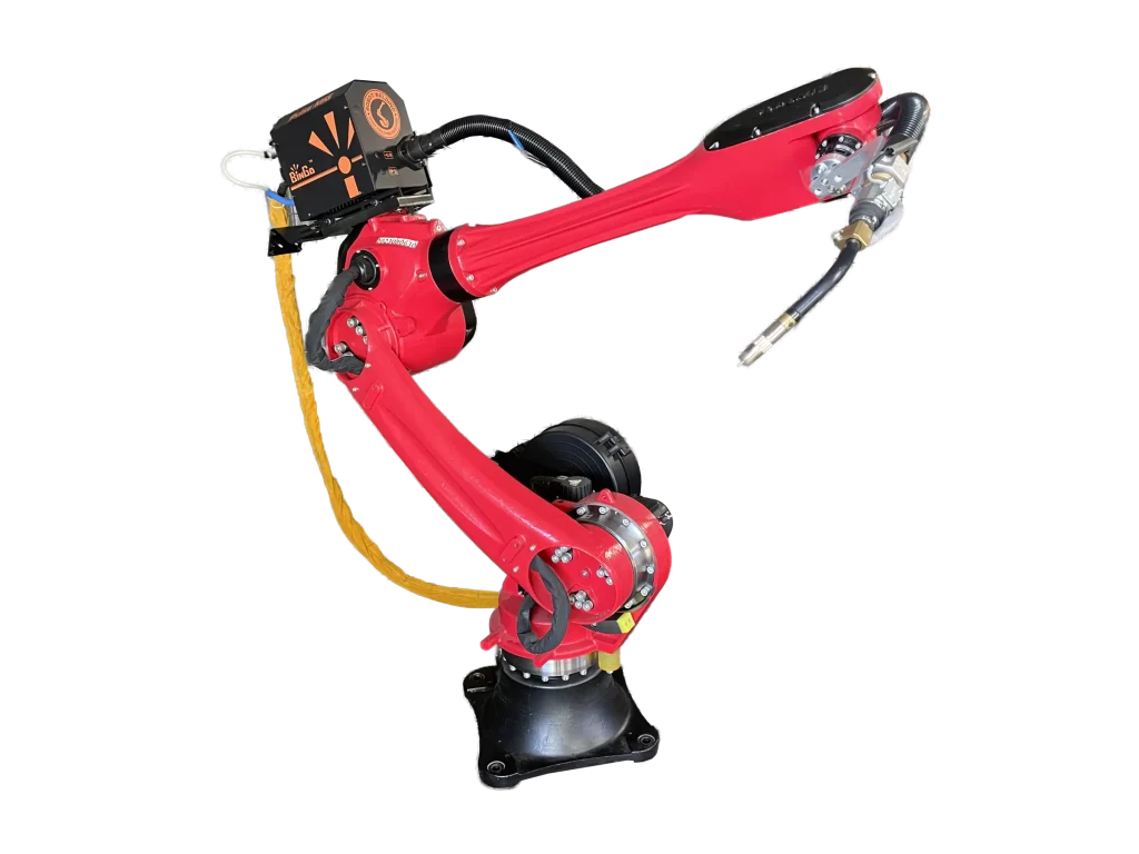
Before sending parts for automation, verify that each weld has a basic symbol, letter and thickness value, execution side, and process number. This is sufficient to ensure the welding robot performs what the designer intended, not what the operator deemed reasonable. Machines that implement these records daily can be found in the Roboteus industrial robots category and among Roboteus laser welders.the welding robot performs what the designer intended , not what the operator deemed reasonable. Machines that implement these records daily can be found in the Roboteus industrial robots category and among Roboteus laser welders.
Frequently asked questions
What does the triangle at the reference line in the drawing mean?
The triangle symbolizes a fillet weld, the most common type in steel structures. The number preceding the triangle, preceded by the letter a or z, indicates the weld thickness. If the triangle is adjacent to a solid line, the weld is made on the arrow side.
What is the difference between dimension a and dimension z of a fillet weld?
Dimension a is the height of the triangle inscribed in the weld cross-section, and dimension z is the length of its side. The same weld always has z greater than a, so confusing the letters changes the filler metal quantity and work time. The drawing uses one of these methods.
How do I record in the drawing that the weld is to be made with a laser?
At the tail of the reference line, the process number according to ISO 4063 is entered, and for laser beam welding it is 52. For comparison, MIG is 131, MAG is 135, and TIG is 141. The absence of a number means that the contractor chooses the method himself.
What does the dashed line under the reference line mean?
This is an identification line, part of the European system according to EN ISO 2553. The symbol placed next to it indicates the weld on the side opposite the arrow. In the American system, this line is absent, and the side is indicated by the symbol’s position above or below the reference line.
How do I read the notation n×l(e) in the weld symbol?
This is an intermittent weld: n is the number of segments, l is the length of each, and e is the distance between them. The notation follows the basic symbol. For the robot, this translates directly into the number of arc ignitions and cycle time.
Sources
- https://roboteus.com/pl/maszyny/roboty-przemyslowe/robot-przemyslowy-rbr-2110s/
- https://roboteus.com/pl/maszyny/spawarki-laserowe/spawarka-laserowa-rbw-1500/
- https://akademianovacert.pl/oznaczanie-spoin-na-rysunku-wedlug-en-iso-2553-system-europejski-a-amerykanski/
- https://inzynierjakosci.pl/2017/11/spoiny-na-rysunku-technicznym/
Editorial note
Symbol descriptions are for illustrative purposes only and do not replace the current version of EN ISO 2553 or ISO 4063. Numerical values in the reading examples are for illustrative purposes only. Welding parameters depend on the machine, material, and process instructions, and the text does not replace the manufacturer’s instructions or occupational health and safety regulations for working with a Class 4 laser.